We Mechanicaltalks, welcome you all to the engineering world. Today, we will know all about cam and follower. It’s definition, types, applications, terminologies etc. are discussed here in detail. So, stay tuned till end!
Cam and follower is a mechanism used to get the desired motion such as reciprocating or translational from an available input, usually rotational.
What is a Cam?
Table of Contents
Cam is the driving component in the mechanism, making sure that the follower follows the desired motion.
Hence, the profile and size of the cam are significant in a cam and follower mechanism.
While designing the mechanism, the main concern goes to getting the appropriate profile of the cam.
What is follower?
The component which gives the desired motion in the mechanism is the follower. The motion of the follower is the output in the cam follower mechanism.
Generally, followers are having two distinct types of motions, oscillating and reciprocating. The followers are designed in such a way that, it always touches the cam during the cam operation.
As the follower moves over the cam, there is friction resistance and side thrust acting. The friction resistance leads to the wear failure of the cam follower mechanism.
Types of cams :
- Disc or Plate Cam
A disk or plate cam is a type of cam where the follower moves radially from the center of rotation of the cam. These cams are popular because of their simple design and compactness that can be installed in remote areas. The use of Disc or Plate Cam is in I.C engines and machine tools.
- Cylindrical Cam
Cylindrical cam is a cam where the cylinder rotates about its axis with a circular cutout in the area of the cylinder. They are also of two types.
In the first type the groove is cut on the surface of the cam and roller and has a positive oscillating movement.
Second one has a cylinder as a working area. In this type of spring-loaded cam follower translates in parallel with the corresponding axis to the rotating cylinder.
- Translating Cam
Translating Cam is a type of cam where the cam can fly in a horizontal plane. Attached follower also has delayed movement with the help of spring. Occasionally groove cams are used when the follower movement is achieved without the use of spring.
- Radial Cam
If the input link i.e. cam, rotates like an angular motion, then the cam has a rotating or angular motion and then we calls it a radial cam.
This profile body is called cam. This has a rotating pair with a basic fixed link or a foundation link. Cam is a revoluting link. There is a pair of switches between the fixed link and the cam and the output link is the follower.
If this cam rotates depending on the profile or position of the cam, the follower will have a translation motion with this prismatic pairing between the adjusted link and the follower.
So the uniform rotating movements of this cam will have a follower navigation and direction.
- Wedge Cam
If the cam has linear movement, then we call it a wedge cam. The Wedge cam has a four-link machine. First a fixed link, a wedge-shaped cam is another link.
Depending on the profile of the wedge, as this cam oscillates in a horizontal direction, the follower will oscillate in a straight line with this prismatic pair or guide.
- Globoidal cam
It has two types one is concave surface and other is convex surface type. A circumferential cut is made on the periphery of the cam for the rotation of the follower. The working of both convex and concave type’s surfaces is same but applications are different. The follower has oscillating motion.
- Conjugate cam
Conjugate cam is combination of two discs. These two discs are perfectly joined together and come in contact with the follower. Here two roller followers are used which constrain opposite to each other. The main advantage of this type of follower is they work noise free and the wear tear rate is very less as compare to other cams. For high speed and high dynamic load applications this cam is best among all.
Types of followers :
Followers are classified in three main categories:
- According to the shape of the follower.
- According to the motion of the follower.
- According to the path of movement of follower.
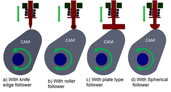
• According to the shape of the follower
A) Knife edge follower
Like its name the follower on the edge of the knife has a sharp knife edge that meets the cam. The movement took place between the cam and the edge of the sharp knife. In this follower, there is a great side between the guide and the followers. It is easy to construct but the use of this follower is very limited because high aging/wear and collapse/tear occur at the contact point.
B) Roller Follower
In the roller follower the cam contact area and the follower are in a rolling position and rolling movements occur between contact areas. So, the chances of wear are very small or to say that they its negligible. Due to the small wear this follower is widely used and the cylindrical roller is free to rotate around the pin joint. This follower has a motion of pure rolling at low speed but when it swings at high speed skidding also happens in it.
In the roller follower the side thrust exist between the guide and the follower sane as the knife edge follower. These types of followers are used when space is not a problem as in aircraft engines and other oil and gas engines etc.
C) Spherical faced follower
For these follower the contact surface is spherical in shape. These are used to reduce the resulting stress that is often seen in the case of flat-faced followers. In the case of flat-faced followers, more stress is produced at higher speed.
Therefore to reduce all these stresses, the flat surface of the follower is converted into a spherical shape, as a result of this change the very small pressures that the follower will cause and can be applied to high-speed engines.
D) Mushroom or flat face followers
As name suggest the contacting surface is as a shape of Mushroom (circular in shape) or flat. There is very less side thrust seen in this case as compare to the roller and knife edge follower which make it stable even at high speed and it does not cause any problem of jamming of cam. It this follower high surface stresses are induced due to the misalignment and deflection, this is the major drawback of this follower. These induced stresses are the reason of high wear. This follower is used in the valve opening mechanism of automobile engine where space available is limited.
• According to the motion of the follower
There are two types of followers according the motion these are –
A) Reciprocating or translating followers
In this type the motion of the follower is reciprocating or translating in the guides where as cam rotates uniformly.
B) Oscillating or rotating followers
In this case the follower oscillates when the cam rotates. The follower is pivoted at a fix position where oscillating or rotating motion in the follower takes place.
• According to the path of movement of follower
According to the movement followers are two types these are as follow-
A) Radial follower
When the line of action of the motion of the follower is passes through the center of rotation of the cam then it is known as the radial follower.
B) Off-set followers
when the line of action of motion of the follower is offset/ away from the center of rotation of the cam then it is known as off-set followers.
Cam and follower terminology :
Some popular terminologies are used widely to describe the properties of any cam and follower, which are given below:
- Cam Profile: Cam profile is the outer surface of the disc cam.
- Base Circle: The base circle is the smallest circle, drawn tangential to the cam profile.
- Trace Point: Tracepoint is a point on the follower, tracepoint motion describes the movement of the follower.
- Pitch Curve: Pitch curve is the path generated by the tracepoint as the follower is rotated about a stationary cam.
- Pitch Point: Pitch point corresponds to the point of maximum pressure angle.
- Prime Circle: This is a circle that drawn tangentially to the pitch curve and concentric to the base circle.
- Pitch Circle: A circle drawn from the cam center and passes through the pitch point is called a Pitch circle.
- Pressure Angle: The pressure angle is the angle between the direction of the follower movement and the normal pitch curve.
Working principle of cam and follower
The operating principle of the Cam and Follower depends on the method of combining both Cam and Follower.
• Cam Mechanism
Cam is a mechanical component which is a rotating circle or eclipse about the minor axis of the Follower.
It can therefore be easily explained that the Cam is the part of the machine that transmits reciprocating, Oscillating or linear movements to the Follower.
Cam shapes are usually oval or an imperfect circle or like an eclipse. If an engineer analyzes an oval Cam then he/she can see the movement that will make an outer hole, which occasionally comes to its place.
This external explosion is very useful and works well for periodic motion. There are two types of Head Cams. The first is a Single Head Cam and the second is a Multiple Head Cam.
• Follower mechanism
The follower is part of a device consideration of which, the Cam rotates in an oscillatory or circular motion. The follower permits the push and pull of the Cam. A follower is used to transfer movement to the required machine part.
The follower rotates in an oscillating or circular arc. The mechanism of cam and the mechanism of the follower are quite supplementary to each other.
The Cam and Follower mechanism is very important in the field of engineering and has many different functions in different machines.
Cam and Follower Importance :
• In the field of mechanical engineering, the Cam-follower method plays an important role in achieving even the distribution of energy in a single machine component.
• By attaching the cylindrical roller to the machine part automatic movement can be achieved by the engineer.
• Cam and Follower can be used on any part of the machine regardless of nut shape and size. Alternatively, a variety of linear movements can be obtained using the mechanism.
• In addition, due to the high durability compared to other bearings Cam-follower can absorb a high amount of shock which increases the mechanical efficiency of the machine part.
• In addition, the operating system is so flexible that it can be used on a soda machine or in aircraft installation. In addition, the machine is also used on the conveyor belt.
• In the case of engines, the camshaft load can be easily designed using the basic crankshaft load system.
• However, flat followers are used by engineers to operate engine valves while roller followers are used by engineers in oil and stationary engines.
Some drawbacks of cams and followers :
• Reversing between camera and cam follower.
• This should be stopped in order to prevent serious damage in the event of a machine crash.
• It is very expensive to make and the machine requires great precision.
• Radius of curvature in negative is not possible.
Application of cam and follower :
• Cam and follower are widely used in operation of inlet and exhaust valve for I C engine.
• These are used in wall clocks.
• These are used in the automatic lathe machine feed.
• Screw pieces of machinery.
• Gear Cutting Machines.
• In Printer, this machine helps the screen to print. The push helps to take the place where the print will do and the pull helps to print on that.
• In Hydraulic Systems, This is the main mechanism.
• Also for Machine Fabrics, the Cam and Follower method helps to sew clothes by pushing and pulling to move.
• In that case, the method of operation depends on the water pressure.
• Default types of equipment, Cam, and follower use for different automated components.
Conclusion: cam and follower
So, after all these explanations, one thing is quite clear that cam and follower is the backbone of any machine or manufacturing industry. Without mechanism of cam and follower, you can’t even imagine any automotive, manufacturing or production industry.
Now, its time to wrap up this conversation. I hope you all like this information. If this was a little bit helpful for you, then do share this with your mates. Also checkout our other contents on this site.
FAQ’s
The size of a cam depends upon?
Base circle
The angle between the direction of the follower motion and a normal to the pitch curve is called?
Pressure angle
A circle drawn with centre as the cam centre and radius equal to the distance between the cam centre and the point on the pitch curve at which the pressure angle is maximum, is called?
Pitch circle
The cam follower generally used in automobile engines is?
Spherical faced follower
The cam follower extensively used in air-craft engines is?
Roller follower
In a radial cam, the follower moves?
In a direction perpendicular to the cam axis
Ofset is provided to a cam follower mechanism to?
Minimise the side thrust
For low and moderate speed engines, the cam follower should move with?
Simple harmonic motion
For high speed engines, the cam follower should move with?
Cycloidal motion
Which of the following displacement diagrams should be chosen for better dynamic performance of a cam-follower mechanism ?
Cycloidal motion.