Hydraulic turbines
Table of Contents
Definition:
It is a device which converts energy stored in a fluid to useful work.In short we can say that it is a device which converts hydraulic energy in to mechanial energy.
Hydraulic turbines were developed in 19th century and widely used in electric power generation till date.
Classification of hydraulic turbines:
ACCORDING TO TYPE OF ENERGY AT INLET
1.) Impulse turbine- Here inlet have only kinetic energy means it’s only kinetic energy consideration turbine.
e.g. Pelton turbine (wheel),Banki turbine,Jonval turbine.
2.) Reaction turbine- Here inlet have both kinetic and pressure energy means it’s both kinetic and pressure energy consideration turbine.
e.g. Francis turbine, Kaplan turbine, propeller turbine.
ACCORDING TO TYPE OF FLOW
1.) Tangential flow- Here water flows in a direction tangential to the path of rotation means perpendicular to both axial and radial direction.
e.g. Pelton turbine.
2.) Radial flow- Here water flows radially to the path of rotation.
e.g. Francis turbine.
3.) Axial flow- Here water flows parallel to the axis of turbine.
e.g. Kaplan, Jonval, Girard turbine.
4.) Mixed flow- In this turbine water enters radially at outer periphery and leaves axially.
e.g. modern Francis turbine.
ACCORDING TO MEASURE OF SPECIFIC SPEED
1.) Low specific speed- In this criteria impulse turbine comes.
e.g. Pelton turbine(10 to 40 r.p.m.).
2.) Medium specific speed- Reaction turbine(Francis turbine- 60 to 300 r.p.m.).
3.) High specific speed- Reaction turbine (Kaplan turbine- 300 to 600 r.p.m.).
ACCORDING TO VALUE OF HEAD
1.) High head- Impulse turbine (Pelton turbine- above 250 m).
2.) Medium head- Reaction turbine (Francis turbine- 60 to 250 m).
3.) High head- Reaction turbine (Kaplan turbine- below 60 m).
Here we can conclude that specific speed of a turbine is inversely proportional to the head under which it works.For example Pelton turbine is a high head turbine but it’s specific speed is too low.
Impulse turbine
Let’s discuss the every part of impluse turbine in detail.
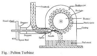
1.) Nozzle and flow regulating arrangement- The amount of water striking the vanes of runner is controlled by providing a spear in the nozzle.The spear is a conical needle which is operated either by a hand wheel or automatically in an axial direction depending upon the size of unit.when the spear is pushed forward in to the nozzle the amount of water striking the runner is reduced.On the other hand,if the spear is pushed back,the amount of water striking the runner increases.
2.) Runner with bucket or vanes- It consists of a circular disk on the periphery of which a number of buckets evenly spaced is fixed.The shape of the bucket is of a double hemispherical cup or bowl.Each bucket is divided in to two symmetrical parts by a dividing wall known as ‘splitter’.
3.) Casing- It is metallic box in which runner and vanes are rotate.The function of casing is to prevent the splashing of the water and to discharge water to tail race.It’s another function is to safeguard against accident.
4.) Tail race- The channel through which discharge of water is done called as tail race.
5.) Surge tank- It is a water storage device used as a pressure neutraliser fitted in the line of penstock.It must be nearest to nozzle.It mainly relieve the pressure when sudden close at the exit of water, hence it prevents from water hammer.
SOME IMPORTANT TERMS
* Water hammer- It is also called as hydraulic shock.when a pipe is suddenly closed at the outlet,the mass of water before the closer end is still moving and thereby the back force of water develop a high pressure that results in shock wave with huge noise and thus pipe becomes failure.
It can be reduced by decreasing the velocity of water which can be done by increasing the dia of pipe.
*Braking jet- When the nozzle is completely closed by moving the spear in forward direction,the amount of water striking the runner reduces to zero.But the runner due to inertia goes on revolving for a long time.To stop the runner in a short time,a small nozzle is provided which strikes the blade in opposite direction.
*Run away speed- when the turbine runs without any load.
Reaction turbine
Reaction turbine means that water at the inlet of turbine posses both kinetic energy and pressure energy.
Generally it is of two type.
1.) Radial flow:
These turbine are those turbine in which water flows in a radial direction.It has two types also.
a.) Inward flow-
In this case water enters from the outer periphery and flows towards the centre of the wheel.
b.) Outward flow-
In this case water enters at the centre of the wheel and their flow is towards the outer periphery of the wheel.
The major application of reaction turbine is a Francis turbine.
* Francis turbine
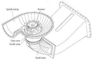
The main parts of a Francis turbine are:
a.) Spiral casing
b.) Runner
c.) Guide vanes
d.) Draft tube
a.) Spiral casing- Here the casing is made spiral to maintain uniform velocity by decreasing cross section area continuosly.
b.) Runner- It is a movable part of Francis turbine which is completely inclosed with air tight casing having full of water.
c.) Guide vanes and guide angle- Guide vanes guide the water to flow in to the turbine.These are aerofoil in shape.
Guide angle is the angle between lift force and resultant force.
d.) Draft tube- Pressure at the exit of runner of reaction turbine is generally less than atmospheric pressure due to high velocity,so water at exit can’t be directly discharge to the tail race.
To avoid this negative pressure a tube of increasing area is used to discharge the water which helps to increase the pressure head of water.This increasing tube is called draft tube.
2.) Axial flow:
If the flow of water parallel to the axis of rotation of shaft then it is called axial flow turbine.
In axial flow turbine the shaft of the turbine is vertical.The lower end which is made larger is called ‘hub’. Generally the vanes are fixed on that hub which acts as runner.
These are of two types;
a.) Kaplan turbine- It is suitable where large quantity of water at low head is available.
It is a modified reaction turbine in which first water enters radially through casing and then enters axially to the turbine.
Here the vanes on the hub are adjustable.
The number of blades in Kaplan turbine is 8.
It is a high load efficiency turbine.
b.) Propeller turbine- The only difference between Kaplan and propeller turbine is that the vanes on the hub are fixed in propeller turbine.
DIFFERENCE BETWEEN IMPULSE AND REACTION TURBINE
1.) In impulse turbine all hydraulic energy is converted into kinetic energy while in reaction turbine only some amount of available energy is converted into kinetic energy.
2.) Degree of reaction of impulse turbine is 0 while it lies between 0 to 1 in reaction turbine.
3.) Discharge is low in impluse turbine while discharge in reaction turbine is medium or high.
4.) Impulse turbine operates at high water heads while reaction turbine operates at lower water head.
5.) In impluse turbine water flow is tangential to the wheel but it’s either axial or radial in reaction turbine.
6.) Impulse turbine requires less maintenance as compared to reaction turbine.
7.) Hydraulic efficiency of impluse turbine is more as compare to reaction turbine.
8.) In impluse turbine there is no draft tube used while in reaction turbine a draft tube is used having increasing area.
9.) In impluse turbine flow is regulated by needle valve fitted in nozzle but in reaction turbine it is done by means of guide vanes assembly.
10.) Water is entered in the form of jets in impluse turbine while in reaction turbine water is admitted over the entire circumference of runner.
11.) Pelton turbine is an example of impluse turbine while Francis, Kaplan turbine are reaction turbines.
That was all about the Hydraulic Turbine. It’s Introduction, classification, working of impluse and reaction turbine. Hope you all like this article. If this was helpful to you then share this article with your well wishers. If you have any doubts regarding this or any mechanical engineering topics then let us know in comment section or contact us through email.
Some images used in mechanical talks is taken from the licensed photo section of Google. We are not taking any kind of credit for all those images


