MILLING OPERATION
Table of Contents
Introduction:
It is the metal removing process which removes metal from a workpiece by rotating a multipoint cutting tool.Due to the use of multipoint cutting tool the material removal rate becomes very higher.The milling machine perform almost all the works which can be performed with the help of a lathe machine, drilling machine,shaper, slotter and planner machine.
Specifications of milling machine:
1.) The maximum length of longitudinal cross wise and vertical travel of table.
2.) Number of spindle speed.
3.) Number of feed and speed of table.
4.) Floor space requirement.
5.) Maximum weight of the machine.
Method of milling:
1.) Peripheral milling
It is the method of milling in which a flat surface is produced which is parallel to the axis of rotation of the cutter.
It is generally of two types.
A.} Conventional or up milling
B.} Climb or down milling
A.} Conventional or up milling
If the rotation of the cutter and the feed of workpiece are opposite to each other,then it is called conventional or up milling.

* Here at the beginning the thickness of chip is minimum and at the end the thickness of chip becomes maximum.
* The cutting force during up milling always try to take the workpiece in upward direction.So to hold the workpiece strong, fixture is required.
* The chip are collected on the unmachined part of the workpiece.So there is a chance that surface finish may harm due to this chip.
* That’s why is not used for finishing operation.It is used only for initial rough operation.
* Here the requirement of cutting force and power is more.
B.} Climb or down milling
If the rotation of the cutter and feeding of workpiece are in same direction, then it is called down milling or climb milling.

* At the beginning of cutting the thickness of the chip is maximum and at the end the thickness of the chip is minimum.
* The cutting force always try to push the workpiece in downward,so it helps fixture.
* The chip always collected on the finished surface,so there is no harm to surface finish.Thats why it is used for finishing operation.
* Since the direction of workpiece and cutter both are same,hence the force and power consumption is less.
2.) Face milling
In this process the flat surface is produced and the the surface is always perpendicular to the axis of rotation of the cutter.
The face milling produced better surface finishing as compared to peripheral milling.
3.) End milling
It is a combination of peripheral and face milling means the cutter has cutting edge on both side i.e. face and periphery.
Milling operations:
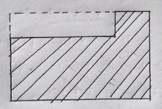
1.) Plane milling
Plane milling operation is performed to generate flat horizontal surface.If we use a peripheral cutter for plane milling operation then it is called ‘slab’ milling.
But if we use a face milling cutter then it is called simply face milling.
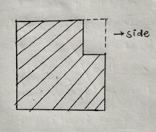
2.) Side milling
This operation is performed to generate a flat vertical surface.
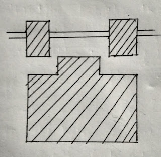
3.) Straddle milling
In this process we produce flat vertical surface on both sides of the workpiece by using two side milling cutter on the same Arbor.
NOTE- The distance between two side cutter are adjusted by spacing collar.
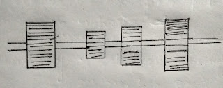
4.) Gang milling
Machining several surfaces with the help of number of cutters having same or different diameter mounted on Arbor is known as Gang milling.
5.) Form milling
Form milling is used to produce irregular contur shape like concave and convex.
6.) End milling
This process is used to produce flat surface which may be vertical, horizontal and inclined at an angle.
It is used to produce slot, groove,key ways etc.
NOTE-
A.} For end milling operation generally we use vertical milling machine.
B.} By using milling we can generate helix on cylindrical body.
We can manufacture gear and cam also.
For these operations one special attachment is used called indexing.
C.} Indexing is a method of dividing the periphery of a job into number of equal parts.
It is used to produce hexagonal or square head of a helix, drill, cutting,gear etc.
GRINDING OPERATION
Grinding is a material removal process in which we use a multipoint cutting tool called grinding wheel which is made from abrasive particles.
Difference between turning and grinding
1.) The rake angle in grinding tool is highly negative such as -60°,-70° etc.
Whereas in case of turning it may be positive, negative or zero.
2.) Grinding is a finishing operation whereas turning is a initial rough operation.
3.) In grinding we use multipoint cutting tool, whereas in case of turning we use single point cutting tool.
4.) In case of grinding due to the use of multipoint cutting tool and also due to highly negative rake angle the requirement of velocity is very high.
Whereas in case of turning operation the cutting speed is comparatively low.
5.) Due to the above reason the specific energy consumption in grinding is very high as compared to turning operation.
6.) The size of chip produced during grinding operation is very small as compared to size of chip in turning operation.
7.) Since grinding is a high speed machining,so most of the heat developed during cutting is taken away by chips itself.
So chips comes out in the form of sparks.
Whereas in case of turning, cutting velocity is low.Thus most of the heat is consumed by tool and workpiece.
Abrasive material used in grinding wheel
There are two types of abrasive particles used for grinding wheel.
1.) Conventional abrasive material
A.} Aluminium oxide (Al2O3)
B.} Silicon carbide.
NOTE- The toughness of Aluminium oxide is more as compared to Silicon carbide.So for grinding tough material like steel, we prefer Aluminium oxide over Silicon carbide.
2.) Super abrasive particles
A.} Cubic boron nitrate
B.} Diamond dust.
NOTE-
a.) Cubic boron nitride is the hardest material after diamond.
b.) Along with the above material we also use Corundum (a crystalline form of Aluminium oxide) as a abrasive material for grinding wheel.
c.) The size of abrasive particle is identified with the help of grit number or mesh number.
TYPE GRIT NUMBER
* Course – 8 to 24
* Medium – 30 to 60
* Fine – 70 to 180
* Very fine – 220 to 600
Bonding material use in grinding wheel
To make the grinding wheel with abrasive particles,some bonding material is required.
We use different types of bonding material such as Vetrified bond(V), Resinoid bond(B),
Silicon bond(S), Rubber bond(R) etc.
1.) Vitrified bond:
It is a ceramic bond.Basically it is a glass.
These bonds are stronger,stiff, porous and resistance to oil,acid and water.Along with this it has certain limitations.
Since it is very brittle in nature,it doesn’t work with high mechanical and thermal shock.
2.) Resinoid bond:
This is basically a thermosetting resin i.e. becomes harden after heating,which is a organic compound.
It is the second most used binding material after Vitrified bond.
It can work with high shock also.
NOTE- Silicon bond and rubber are also used as bonding material.
Rubber is specially used for Abrasive saw because of its flexibility.
Specification of grinding wheel
Let’s take an example and try to understand.
51 A 60 K 6 V 05
1.) 51- This is manufacturer identification.
It is optional,it identifies exact kind of abrasive.
2.) A- It represent type of abrasive.
For example,A- Aluminium oxide,B- Boron carbon nitrate etc.
3.) 60- Average grit size. i.e.
Course (8 to 24), Medium (30 to 60),Fine (70 to 180),Very fine ( 220 to 600).
4.) K- Hardness of wheel i.e. Bonding strength.It varies from A to Z.
A for softest and Z for hardest.
5.) 6- It represents porosity of wheel.It varies from 1 to 20.
1 represents low porosity.
20 represents high porosity.
NOTE- In case of diamond we don’t use porosity but we use diamond concentration.It varies from 25 to 100.
6.) V- It represents bonding material.
Here, V- vitrified bond
B- resin bond
S- silicon bond
R- rubber bond
7.) 05- It is also manufacturer identification.
NOTE- In case of grinding wheel we provide porosity, because it works as a clearance and it also helps in cooling of grinding wheel.
Technical terms used in Grinding
1.) Glazing
It represents the excessive wear of grinding wheel.This makes the grinding wheel dull in cutting but shinning in looking.By proper dressing of grinding wheel this problem can be removed.
2.) Loading or clogging
Loading and clogging represents the decrease in porosity of the grinding wheel.
The porosity decreases when the pours are filled with small chips.
It is mostly comes into picture while grinding soft material.
This can also be eliminated by dressing of grinding wheel.
3.) Dressing
It is the operation performed on the grinding wheel for conditioning of the surface of grinding wheel.
It is performed to reuse grinding wheel after glazing and loading.
We use single point diamond tool for dressing of grinding wheel in which small amount of material is removed from structure of grinding wheel.
4.) Truing
It is performed for correcting the geometry of grinding wheel.
* Grinding ratio:
This ratio represents the volume of removed from workpiece to the volume of material removed from grinding wheel.
For conventional grinding machine it varies from 20:1 to 80:1,but it may be up to 200:1.
NOTE- Soft wheel is used for hard material whereas hard wheel is used for grinding soft material.
Grinding operations
Generally we perform four types of grinding operations.
1.) Surface grinding
It is mostly used grinding operation.
This machine is similar to milling machine.
2.) Cylindrical grinding
The cylindrical grinding is used for smaller size cylindrical job.This machine is similar to lathe machine.
3.) Internal grinding
The least used grinding operation is internal grinding.It is performed in internal surface of bearing or bushes.
4.) Centerless grinding
This grinding operation is performed on long and hollow cylindrical object such as pipe.The word centerless is used because there is no center such as life or dead center because object is hollow.
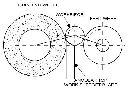
NOTE-
A.} Direction of rotation of both wheel are same.
B.} Plate is used for positioned the job.
C.} Feed wheel is made of rubber and used to provide feed to job.
That was all about the milling and grinding operations. Hope you all like this article. If this was helpful to you then share this article with your well wishers. If you have any doubts regarding this or any mechanical engineering topics then let us know in comment section or contact us through email.
Some images used in mechanical talks is taken from the licensed photo section of Google. We are not taking any kind of credit for all those images